From Teltonika Security Wiki
Immobilizers > IMB5 Installation Manual
IMB5 Installation Manual
IMB5 Vehicle Immobilizer
System Unit and ID card
|
| Purpose
|
Car theft prevention
|
| Technology
|
2-way encrypted RF
|
| Frequency
|
2.4 GHz
|
| Temperature
|
-40°C to +85°C
|
IMB5 Immobilizer Purpose
The purpose of the immobilizer "TELTONIKA" is car theft prevention.
- The driver is identified when the ID card is present inside the communication area.
- If no ID card is present, the device prevents engine start or shuts down the running engine.
- Up to 5 ID cards and one radio relay (IMB6) can be paired with the System unit.
Specifications
| Parameter |
Value
|
| Operating temperature range |
-40°C to +85°C
|
| Supply voltage |
9-15 VDC
|
| Average consumption current |
Up to 10 mA (at 12V)
|
| Average control distance |
2-4 meters
|
| Communication frequency |
2.4 GHz
|
| Pulse radiated power |
up to 1 mW
|
Wiring Diagram Connections
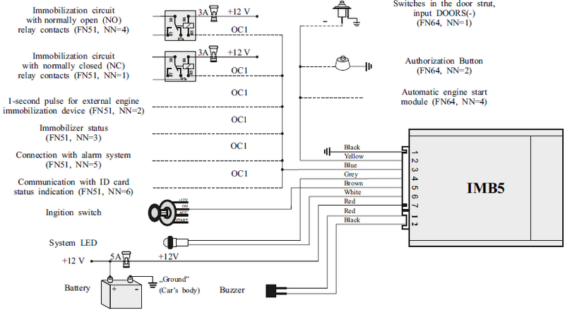 IMB5 Connection Scheme
| Wire Color |
Connection / Function
|
| Black |
Ground (Car's body)
|
| Red |
+12V Battery
|
| Yellow |
Ignition switch
|
| Blue |
OC1 (Optional Control 1)
|
| Grey |
Buzzer
|
| Brown |
Authorization Button / Doors (-) Input
|
Entering Service Mode
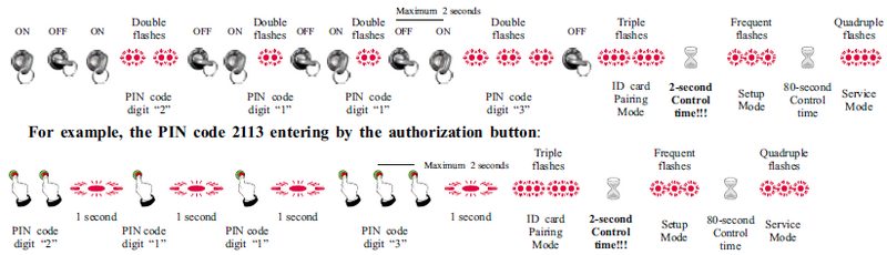 PIN code entering logic
PIN Entering Steps (Example 2113)
To enter the service or pairing mode, follow these manual steps:
- By Ignition: Turn ignition ON/OFF and count System LED flashes. Wait for double flashes to confirm each digit.
- By Button: Press and hold the button for 1 second for each unit of the digit (e.g., for digit "2" press twice).
- Mode Confirmation: After the last digit, wait for:
- Triple flashes: ID card Pairing Mode.
- Quadruple flashes: Full Service Mode.
PIN Timing Requirements
- **Maximum 2 seconds:** The time allowed between ignition turns or button presses.
- **80-second Control time:** The duration the system stays in Setup Mode before timing out.
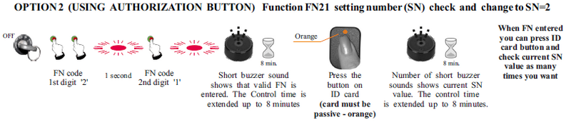
Changing Settings (FN and SN)
Step 1: Entering Function Number (FN)
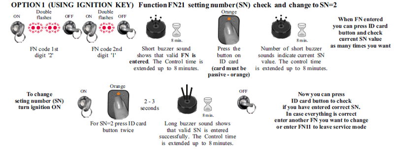 Option 1 and Option 2 for FN entering
Step 2: Changing Setting Number (SN)
 Changing SN - Part 1
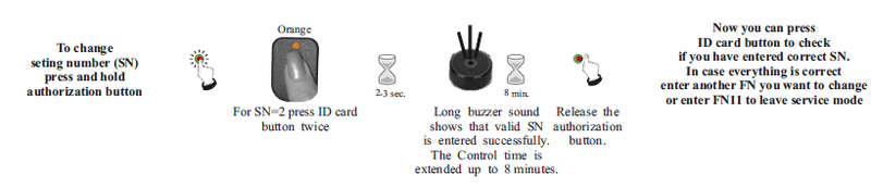 Changing SN - Part 2
Full Immobilizer Settings Table (FN and SN)
| FN |
Function |
SN |
Setting Description |
EU |
IMB5
|
| FN=11 |
END OF FN SETTINGS |
— |
Exit service mode |
✔ |
ⓥ
|
| FN=21 |
IMMOBILIZATION SIGNAL |
SN=1 |
Signal ON 20s after ignition OFF |
✔ |
ⓥ
|
| SN=2 |
Immobilization signal is turned OFF |
✔ |
|
| FN=22 |
ANTI-CARJACK |
SN=1 |
Anti-carjack is turned OFF |
✔ |
ⓥ
|
| SN=2 |
Triggered by ignition ON or card loss. 120s countdown. |
— |
|
| SN=3 |
Triggered by ignition ON or card loss. 60s countdown. |
— |
|
| SN=4 |
Triggered by ignition ON or door opening. 60s countdown. |
— |
|
| FN=23 |
SIGNAL DURING ANTI-CARJACK |
SN=1 |
Transfer to OC1 or external equipment (immediate) |
— |
ⓥ
|
| SN=2 |
Transfer to OC1 or external equipment (delayed start) |
— |
|
| SN=3 |
Gradual "soft" immobilization signal transfer to OC1 |
— |
|
| FN=43 |
ID CARD SIGNAL LOST WARNING |
SN=1 |
Warning is ON (buzzer every 5s for 3min) |
✔ |
ⓥ
|
| SN=2 |
Warning is OFF |
✔ |
|
| FN=45 |
LOW ID CARD BATTERY WARNING |
SN=1 |
Warning is ON (4 double buzzer signals) |
✔ |
ⓥ
|
| SN=2 |
Warning is OFF |
✔ |
|
| FN=51 |
IMMOBILIZATION SIGNAL (OC1) |
SN=1 |
OC1 used for relay with Normally Closed (NC) contacts |
✔ |
ⓥ
|
| SN=2 |
Negative 1s pulse for external equipment |
✔ |
|
| SN=3 |
Negative polarity signal transferred to OC1 |
✔ |
|
| SN=4 |
OC1 used for relay with Normally Open (NO) contacts |
✔ |
|
| SN=5 |
Communication with alarm system (compatible list) |
✔ |
|
| SN=6 |
Constant negative polarity if ID card is OK (5s delay) |
✔ |
|
| SN=7 |
Constant negative polarity if ID card is OK (0.7s delay) |
✔ |
|
| FN=61 |
AUTHORIZATION BUTTON PRESS |
SN=1 |
Single press within 5s after ignition ON |
✔ |
ⓥ
|
| SN=2 |
Double press within 5s after ignition ON |
✔ |
|
| FN=64 |
INPUT 'DOORS (-)' PURPOSE |
SN=1 |
Doors (-) input |
✔ |
ⓥ
|
| SN=2 |
Authorization button (-) input |
✔ |
|
| SN=3 |
Not used |
✔ |
|
| SN=4 |
AUTOSTART (-) input. Disables immobilization when active. |
— |
|
| FN=81 |
CHANGE THE PIN |
— |
Start PIN code change procedure |
✔ |
✔
|
| FN=82 |
IMB6 PIN CODE INDICATION |
SN=1 |
Turn ON ignition to guide PIN code entering for IMB6 |
✔ |
✔
|
| FN=91 |
RESTORE FACTORY DEFAULTS |
SN=1 |
Restore all default settings and PIN code |
✔ |
ⓥ
|
| FN=92 |
CONFIGURATION DATA UPLOAD |
SN=1 |
IMB5 uploads configuration to Wireless Relay IMB6 |
✔ |
✔
|
Safety Warning
The user MUST change the PIN code after the installation and do not save it inside the car.


